Tutorial 3 of Chapter 11 (Keying) from The Foundry NukeX 7 for Compositors textbook:
In this tutorial, you will pull a key using the IBKColor and IBKGizmo nodes. Figures 1 displays the input green screen image and final composite, respectively.
Step – 1
Navigate to http://www.hollywoodcamerawork.us/greenscreenplates.html and download Hair Detail clip. Next, extract content of zip file to your hard drive.
Step – 2
Start a new script in Nuke. Read in the Hair Detail clip you have downloaded; the Read1 node is inserted in the Node Graph panel. Next, press 1 to display the output of the Read1 node in the Viewer1 panel.
Step – 3
Select the Read1 node in the Node Graph panel and then choose the Keyer button from the Nodes toolbar; the Keyer menu is displayed. Next, choose IBKColour from the menu; the IBKColourV3_1 node is inserted in the Node Graph panel. Notice that the output is black in the Viewer1 panel. Next, you will rectify it.
Step – 4
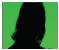
In the Parameters tab of the IBKColourV3_1 node properties panel, select green from the screen type drop-down; the output of the IBKColourV3_1 is displayed in Viewer1 panel, as shown in Figure 2.
Step – 5
Enter -0.037 in the g field corresponding to the darks parameter.
Step – 6
Enter 0.16 in the g field corresponding to the lights parameter; the output is displayed in the Viewer1 panel, as shown in Figure 3.
Step – 7
Enter 0.86 in the erode field.
Step – 8
Enter 7 in the patch black field; a clean plate is created, as shown in Figure 4.
Step – 9
Click on the empty area of the Node Graph panel and then choose the Keyer button from the Nodes toolbar; the Keyer menu is displayed. Next, choose IBKGizmo from the menu; the IBKGizmoV3_1 node is inserted in the Node Graph panel.
Step – 10
Press and hold the left mouse button on the fg input of the IBKGizmoV3_1 node and then drag the cursor to the Read1 node; a connection is established between the IBKGizmoV3_1 and Read1 nodes.
Step – 11
Press and hold the left mouse button on the input c of the IBKGizmoV3_1 node and then drag the cursor to the IBKColorV3_1 node; a connection is established between the IBKColorV3_1 and IBKGizmoV3_1 nodes.
Step –12
Make sure IBKGizmoV3_1 is selected in the Node Graph panel and then press 1; the output of the IBKGizmoV3_1 node is displayed in the Viewer1 panel.
Step – 13
In the IBK tab of the IBKGizmoV3_1 node properties panel, select C-green from the screen type drop-down.
Step – 14
Hover the cursor over the Viewer1 panel and then press A; the alpha channel is displayed in the Viewer1 panel, as shown in Figure 5. Now, press A again to switch to the color channels.
Step –15
Click on the empty area of the Node Graph panel to deselect the selected nodes, if any. Next, choose the Draw button from the Nodes toolbar; the Draw menu is displayed. Now, choose Grid from the menu; the Grid1 node is inserted in the Node Graph panel.
Step –16
Select the IBKGizmoV3_1 node in the Node Graph panel and then press M; the input A of the Merge1 node is connected with the IBKGizmoV3_1 node.
Step – 17
Press and hold the left mouse button on the input B of the Merge1 node and drag the cursor to the Grid1 node; a connection is established between the Merge1 and Grid1 nodes. The output of the Merge1 node is displayed in the Viewer1 panel. In the Grid tab of the Grid1 node properties panel, enter 64 in the size field; the grid pattern behind the character is changed.
Step –18
Choose File > Save from the menu bar to save the script.
In this tutorial, you will pull a key using the IBKColor and IBKGizmo nodes. Figures 1 displays the input green screen image and final composite, respectively.
 |
| Figure 1 - The input (left) and final (right) images displayed |
Navigate to http://www.hollywoodcamerawork.us/greenscreenplates.html and download Hair Detail clip. Next, extract content of zip file to your hard drive.
Step – 2
Start a new script in Nuke. Read in the Hair Detail clip you have downloaded; the Read1 node is inserted in the Node Graph panel. Next, press 1 to display the output of the Read1 node in the Viewer1 panel.
Step – 3
Select the Read1 node in the Node Graph panel and then choose the Keyer button from the Nodes toolbar; the Keyer menu is displayed. Next, choose IBKColour from the menu; the IBKColourV3_1 node is inserted in the Node Graph panel. Notice that the output is black in the Viewer1 panel. Next, you will rectify it.
Step – 4
In the Parameters tab of the IBKColourV3_1 node properties panel, select green from the screen type drop-down; the output of the IBKColourV3_1 is displayed in Viewer1 panel, as shown in Figure 2.
 |
| Figure 2 The output of the IBKColourV3_1 node |
Enter -0.037 in the g field corresponding to the darks parameter.
Step – 6
Enter 0.16 in the g field corresponding to the lights parameter; the output is displayed in the Viewer1 panel, as shown in Figure 3.
 |
| Figure 3 The output after setting values of the darks and lights parameters |
Enter 0.86 in the erode field.
Step – 8
Enter 7 in the patch black field; a clean plate is created, as shown in Figure 4.
 |
| Figure 4 The clean plate displayed |
The r, g, and b fields corresponding to the darks and lights parameters are used to separate the black color and the screen color (green in this case). The erode field is used to correct the foreground edges. You can use the patch black field to remove the black color from the output image but before using this field make sure that you have separated the black color and the screen color using the darks and lights parameters.
Step – 9
Click on the empty area of the Node Graph panel and then choose the Keyer button from the Nodes toolbar; the Keyer menu is displayed. Next, choose IBKGizmo from the menu; the IBKGizmoV3_1 node is inserted in the Node Graph panel.
Step – 10
Press and hold the left mouse button on the fg input of the IBKGizmoV3_1 node and then drag the cursor to the Read1 node; a connection is established between the IBKGizmoV3_1 and Read1 nodes.
Notice that the IBKGizmoV3_1 node has three input connectors, namely bg, c, and fg. The input bg is used to connect a background image. This image is used to calculate the edge details. The input c is used to connect an IBKColor node. You can also connect a clean plate to it. The clean plate produces finer results than the IBKColor node.
Step – 11
Press and hold the left mouse button on the input c of the IBKGizmoV3_1 node and then drag the cursor to the IBKColorV3_1 node; a connection is established between the IBKColorV3_1 and IBKGizmoV3_1 nodes.
Step –12
Make sure IBKGizmoV3_1 is selected in the Node Graph panel and then press 1; the output of the IBKGizmoV3_1 node is displayed in the Viewer1 panel.
Step – 13
In the IBK tab of the IBKGizmoV3_1 node properties panel, select C-green from the screen type drop-down.
The options in the screen type drop-down are used to select the screen type. Select C-blue option from it if the foreground image is a blue screen image. For green foreground image, select C-green option from this drop-down. If you select the pick option from this drop-down, you can replace the input c with a single color. In this case, the BKGizmoV3_# node will behave like a traditional keyer.
Step – 14
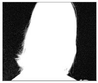
Hover the cursor over the Viewer1 panel and then press A; the alpha channel is displayed in the Viewer1 panel, as shown in Figure 5. Now, press A again to switch to the color channels.
 |
| Figure 5 The alpha channel displayed |
Click on the empty area of the Node Graph panel to deselect the selected nodes, if any. Next, choose the Draw button from the Nodes toolbar; the Draw menu is displayed. Now, choose Grid from the menu; the Grid1 node is inserted in the Node Graph panel.
Step –16
Select the IBKGizmoV3_1 node in the Node Graph panel and then press M; the input A of the Merge1 node is connected with the IBKGizmoV3_1 node.
Step – 17
Press and hold the left mouse button on the input B of the Merge1 node and drag the cursor to the Grid1 node; a connection is established between the Merge1 and Grid1 nodes. The output of the Merge1 node is displayed in the Viewer1 panel. In the Grid tab of the Grid1 node properties panel, enter 64 in the size field; the grid pattern behind the character is changed.
Step –18
Choose File > Save from the menu bar to save the script.
No comments:
Post a Comment